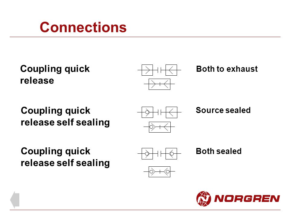
Hydraulic Quick Connect Symbol

Self Sealing Couplings From Walther Prazision

Industrial Hydraulic Symbol Explanation Stuffworking Com
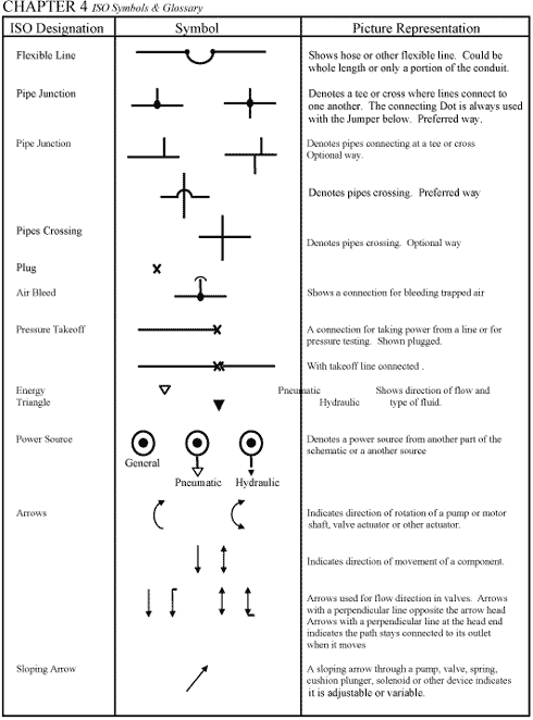
Chapter 4 Iso Symbols Hydraulics Pneumatics
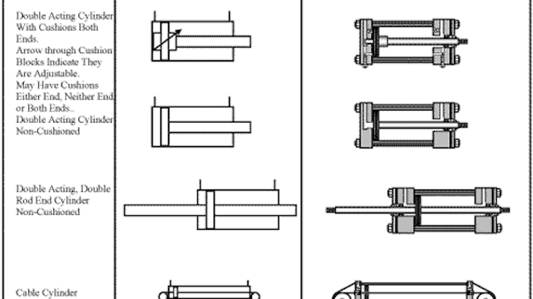
Chapter 4 Iso Symbols And Glossary Part 3 Hydraulics Pneumatics
For System Diagrams And Component Identification Ppt Download
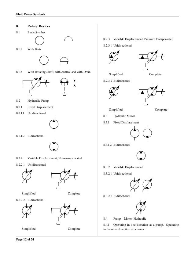
Fluid Power Graphic Symbols
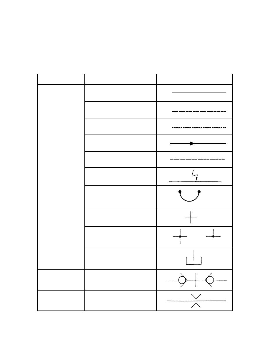
The most common p id symbols are listed below.
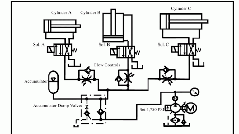
Hydraulic quick connect symbol.
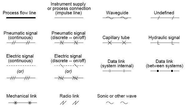
P Id Symbols Complete List Pdf Projectmaterials
Standard Hydraulic Symbols

Vektek Products Hydraulic Pallet Fixture Accessories Tombstone Top Plates

Hydraulic Symbology 206 Motors And Actuators
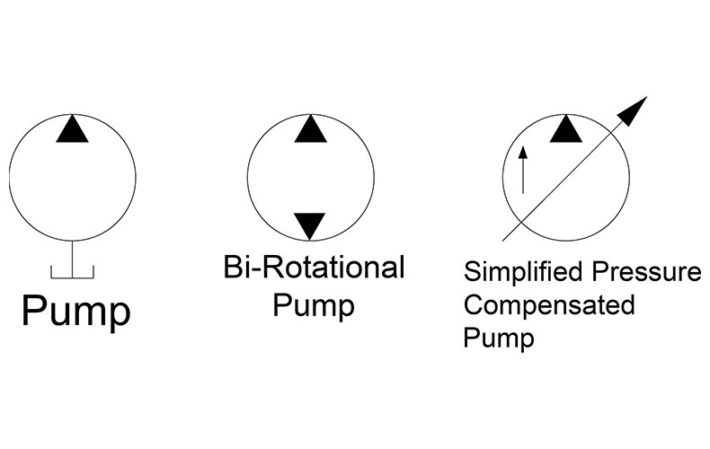
Hydraulic Symbology 205 Hydraulic Pumps
Hydraulic Pneumatic And P Id Schematics In Autocad Electrical Imaginit Manufacturing Solutions Blog

Tx 6683 Hydraulic Diagram Symbols Wiring Diagram

Flow Chart Symbols Mechanical Engineering Design Piping And Instrumentation Diagram Process Engineering

Hydraulic Symbology 201 Industrial Directional Valves
Hydraulic Coupling Connectors Manufacturers Quick Connect Disconnect Hydraulic Fittings Safeway Custom Fluid Transfer Formerly Safeway Hydraulic
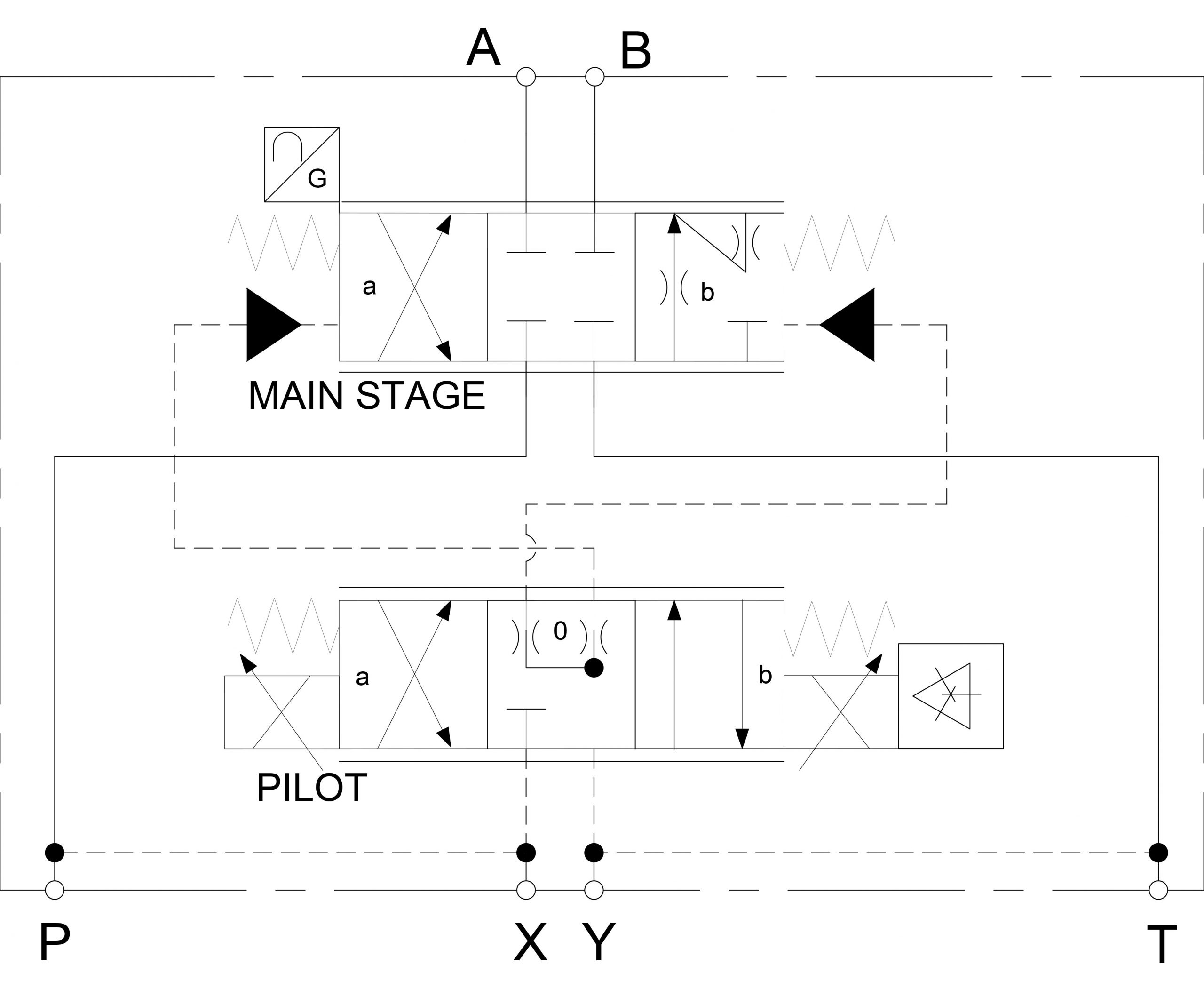
Hydraulic Symbology 302 High Response Valves
Material Iso Cetop Hydraulic Symbols Graphics Meanings Examples Heavy Equipment

Hydraulic Symbology 202 Stacked And Piloted Industrial Valves

Chapter 18 Miscellaneous Fluid Power Items Hydraulics Pneumatics

Book 2 Chapter 19 Rotary Actuators Hydraulics Pneumatics

What S The Difference Between Hydraulic Circuit Symbols Machine Design In 2020 Circuit Hydraulic Symbols
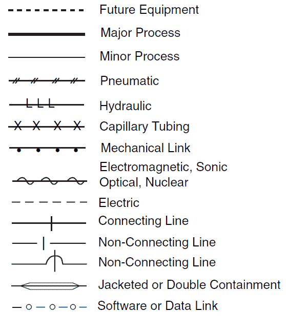
P Id And Pfd Drawing Symbols And Legend List Pfs Pefs
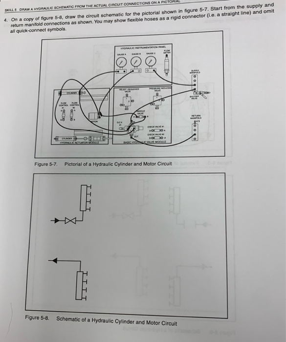
Procedure Overview In This Procedure You Will Dra Chegg Com
Https Encrypted Tbn0 Gstatic Com Images Q Tbn 3aand9gcqtun4kzwdkqxe4loxy5d7 M8df Sqvlrurmamridk Ltubrbnd Usqp Cau
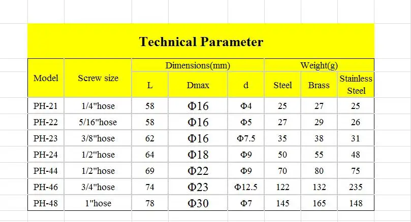
Ph Hydraulic Pneumatic Hose Quick Coupling 1 4 To 1 Air Hose Coupler Types Quick Coupling Hose Quick Couplingquick Coupling Hydraulic Aliexpress
Chapter 5 Pneumatic And Hydraulic Systems Hydraulics Pneumatics

4 Sets 1 2 Flat Face Hydraulic Quick Connect Couplers Couplings Skid Steer Us Ebay In 2020 Ebay Hydraulic Bobcat Skid Steer

Hydraulic Power Pack This Ebook Answer You All Questions About Hydraulic Power Unit
Hydraulic Products Pumps Motors Valves More Hydraulic Specialty
Source : pinterest.com
